2017年9月24日星期日

Renohopmt share with you Automatic Fixture Design

Renohopmt share with you Automatic Fixture Design 
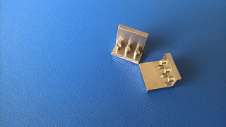
China precision machining Traditional synchronous grippers for assembly equipment move parts to the gripper centre-line, assuring that the parts will be in a known position after they arc picked from a conveyor or nest. However, in some applications, forcing the part to the centre-line may damage cither the part or equipment. When the part is delicate and a small collision can result in scrap, when its location is fixed by a machine spindle or mould, or when tolerances are tight, it is preferable to make a gripper comply with the position of the part, rather than the other way around. For these tasks, Zaytran Inc. Of Elyria, Ohio, has created the GPN series of non- synchronous, compliant grippers. Because the force and synchronizations systems of the grippers are independent, the synchronization system can be replaced by a precision slide system without affecting gripper force. Gripper sizes range from 51b gripping force and 0.2 in. stroke to 40Glb gripping force and 6in stroke.
 China precision machining Grippers Production is characterized by batch-size becoming smaller and smaller and greater variety of products. Assembly, being the last production step, is particularly vulnerable to changes in schedules, batch-sizes, and product design. This situation is forcing many companies to put more effort into extensive rationalization and automation of assembly that  was  previouslyextensive rationalization and automation of assembly that was previously the case. Although the development of flexible fixtures fell quickly behind the development of flexible handling systems such as industrial robots, there are, nonetheless promising attempts to increase the flexibility of fixtures. The fact that fixtures are the essential product - specific investment of a production system intensifies the economic necessity to make the fixture system more flexible. 
   China precision machining Fixtures can be divided according to their flexibility into special fixtures, group fixtures, modular fixtures and highly flexible fixtures. Flexible fixtures are characterized by their high adaptability to different workpieces, and by low change-over time and expenditure.  
    There are several steps required to generate a fixture, in which a workpiece is fixed for a production task. The first step is to define the necessary position of the workpiece in the fixture, based on the unmachined or base pan, and the working features. Following this, a combination of stability planes must be selected. These stability planes constitute the fixture configuration in which the workpiece is fixed in the defined position, all the forces or torques are compensated,
and the necessary access to the working features is ensured. Finally, the necessary positions of moveable or modular fixture elements must be calculated- adjusted, or assembled, so that the workpiece is firmly fixed in the fixture. Through such a procedure the planning and documentation of the configuration and assembly of fixture can be automated. 

    The configuration task is to generate a combination of stability planes, such that fixture forces in these planes will result in workpiece and fixture stability. This task can be accomplished conventionally, interactively or in a nearly fully automated manner. The advantages of an interactive or automated configuration determination are a systematic fixture design process, a reduction of necessary designers, a shortening of lead time and better match to the working conditions. In short, a significant enhancement of fixture productivity and economy can be achieved China precision machining.
2017年9月10日星期日

Precision parts processing Surface Hardening of Nitriding

Precision parts processing Surface Hardening of Nitriding
    Precision CNC machining parts Nitriding is somewhat similar to ordinary case hardening, but it uses a different material and treatment to create the hard surface constituents.
In this process the metal is heated to a temperature of around 950(510) and held there for a period of time in contact with ammonia gas. Nitrogen from the gas  is introduced into the steel, forming very  hard nitrides that are finely dispersed through the surface metal.
   Nitrogen has greater hardening ability with certain elements than with others, hence, special nitriding alloy steels have been developed.
  Precision CNC machining parts Aluminum in the range of 1% to 1.5% has proved to be especially suitable in steel, in that it combines with the gas to form a very stable and hard constituent. The temperature of heating ranges from 925 to 1,050(495~565).
   Liquid nitriding utilizes molten cyanide salts  and, as in gas nitriding, the temperature is held below the transformation range. Liquid nitriding adds more nitrogen and less carbon than either cyaniding or carburizing in cyanide baths.
Case thickness of 0.001 to 0.012in.(0.03~0.30mm) is obtained, whereas for gas nitriding the case may be  as thick as 0.025 in.(0.64mm). In general the uses of the two-nitriding processes are similar.
   Nitriding develops extreme hardness in the surface of steel. This hardness ranges from 900 to 1,100 Brinell, which is considerably higher than that obtained by ordinary case hardening.
Nitriding steels, by virtue of their alloying content, are stronger than ordinary steels and respond readily to heat treatment. It is  recommended that these steels be machined and heat-treated before nitriding, because there is no scale or further work necessary after this process.
 Precision CNC machining parts Fortunately, the interior structure and properties are not affected appreciably by the nitriding treatment and, because no quenching is necessary, there is little tendency to  warp, develop cracks, or change condition in any way. The surface effectively resists corrosive action of water, saltwater spray, alkalies, crude oil, and natural gas.

 Precision CNC machining parts


2017年9月3日星期日

Types of Casting And manufacturing process

Types of  Casting  And manufacturing process

    Precision CNC machining parts Casting is a manufacturing process in which molten metal is poured or injected and allowed to solidify in a suitably  shaped mold cavity. During or after  cooling, the cast part is removed from the mold and then processed for delivery.
    Casting processes and cast-material technologies vary from simple to highly complex. Material and process selection  depends on the part’s complexity and function, the product’s quality specifications, and the projected cost  level.
     Castings are parts that are made close to their final dimensions by a casting process. With a history dating back 6,000  years, the various casting processes are  in a state of continuous refinement and evolution as technological advances are being made.
A:Sand Casting  
    Sand casting is used to make large parts (typically iron, but also bronze, brass, aluminum). Molten metal is poured into a mold cavity formed out of sand (natural or synthetic).
    The processes of sand casting are discussed in this section, including patterns, sprues and runners, design considerations, and casting allowance.
    The cavity in the sand is formed by using a pattern (an approximate duplicate of the real part), which are typically made out of wood, sometimes metal. The cavity is contained in an aggregate housed in a box called the flask.
    Core is a sand shape inserted into the mold to produce the internal features of the part such as holes or internal passages. Cores are placed in the cavity to form holes of the desired shapes. Core print is the region added to the pattern, core, or mold that is used to locate and support the core within the mold.
  Precision CNC machining parts  A riser is an extra void created in the mold to contain excessive molten material. The purpose of this is to feed the molten metal to the mold cavity as the molten metal solidifies and shrinks, and thereby  prevents voids in the main casting.
    In a two-part mold, which is typical of sand  castings, the upper half, including the top half of the pattern, flask, and core is called cope and  the lower half is called drag,  The parting line or the parting surface is line or surface that separates the cope and drag.
    The drag is first filled partially with sand, and the core  print, the cores, and the gating system are  placed near the parting line. The cope is then assembled to the drag, and the sand is poured on the cope half, covering the pattern, core and the gating system.
    The sand is compacted by vibration and mechanical means. Next, the cope is removed from the drag, and the pattern is carefully removed. The object is to remove the pattern without breaking the mold cavity.
    This is facilitated by designing a draft, a slight angular offset from the vertical to the vertical surfaces of the pattern. This is usually a minimum of 1.5mm(0.060in.), whichever is greater. The rougher the surface of the pattern, the more the draft to be provided.
    The molten material is poured into the pouring cup, which is part of the gating system that supplies the molten material to the mold cavity.
    Precision CNC machining partsThe vertical part of the gating system connected to the pouring cup is the sprue, and the horizontal portion is called the runners and finally to the multiple points where it is introduced to the mold cavity called the gates.