2015年3月30日星期一

Robots already in use everywhere

Robots already in use everywhere
 Sales of industrial robots cnc machining  have risen to record levels and they have huge, untapped potential for domestic chores like mowing the lawn and vacuuming the carpet. Last year 3,000 underwater robots, 2,300 demolition robots and 1,600 surgical robots were in operation. A big increase is predicted for domestic robots for vacuum cleaning and lawn mowing, increasing from 12,500 in 2000 to almost 500,000 by the end of 2004. IBot Roomba floor cleaning robot is now available at under $200.00.  
 In the wake of recent anthrax scares, robots are increasingly used in postal sorting applications. Indeed, there is huge potential to mechanize the US postal service. Some 1,000 robots were installed last year to sort parcels and the US postal service has estimated that it has the potential to use up to 80,000 robots for sorting.
  Look around at the robots around us today: automated gas pumps, bank ATMs, self-service checkout lanesmachines that are already replacing many service jobs. 
Fast-forward another few decades. It doesn't require a great leap of faith to envision how advances in image processing, microprocessor speed and human-simulation could lead to the automation of most boring, cnc machining  low-intelligence, low-paying jobs.
  Marshall Brain (yes, that's his name) founder of HowStuffWorks.com has written a couple of interesting essays about robotics in the future, well worth reading. He feels that it is quite plausible that over the next 40 years robots will displace most human jobs. According to Brain's projections, in his essay "Robotic Nation", humanoid robots will be widely available by 2030. They will replace jobs currently filled by people for work such as fast-food service, housecleaning and retail sales. Unless ways are found to compensate for these lost jobs, Brain estimates that more than 50% of Americans could be unemployed by 2055 replaced by robots. 
  Intelligent robots will be everywhere

  The world of HAL and Data, of sentient machines, is fast approaching. Indeed, in some ways it has already arrived as humanlike machines increasingly take on the work of humans. As processing power increases exponentially, and as MEMS technology brings smaller and smarter sensors and actuators, robots are the breeding ground for future-generation products with new, cnc machining varied and exciting applications.
 
 cnc machining

2015年3月28日星期六

Boosting Competitiveness

Boosting Competitiveness  
 As mentioned, robotic China metal parts machining  applications originated in the automotive industry. General Motors, with some 40-50,000 robots, continues to utilize and develop new approaches. The ability to bring more intelligence to robots is now providing significant new strategic options. Automobile prices have actually declined over the last two to three years, so the only way that manufacturers can continue to generate profits is to cut structural and production costs.
   When plants are converted to new automobile models, hundreds of millions of dollars are typically put into the facility. The focus of robotic manufacturing technology is to minimize the capital investment by increasing flexibility. New robot applications are being found for operations that are already automated with dedicated equipment. Robot flexibility allows those same automated operations to be performed more consistently, with inexpensive equipment and with significant cost advantages.
 Robotic Assistance
 A key robotics growth arena is Intelligent Assist Devices (IAD).operators manipulate a robot as though it were a bionic extension of their own limbs with increased reach and strength. This is robotics technology not replacements for humans or robots, but rather a new class of ergonomic assist products that helps human partners in a wide variety of ways, including power assist, motion guidance, line tracking and process automation. 
  IAD use robotics technology to help production people to handle parts and payloads, more, heavier, better, faster,China metal parts machining   with less strain. Using a human-machine interface, the operator and IAD work in tandem to optimize lifting, guiding and positioning movements. Sensors, computer power and control algorithms translate the operator's hand movements into super human lifting power.
New robot configurations
  As the technology and economic implications of Moore's law continue to shift computing power and price, we should expect more innovations, more cost-effective robot configurations, more applications beyond the traditional service emphasis.
  The biggest change in industrial robots is that they will evolve into a broader variety of structures and mechanisms. In many cases, configurations that evolve into new automation systems won't be immediately recognizable as robots. For example, robots that automate semiconductor manufacturing already look quite different from those used in automotive plants.

   We will see the day when there are more of these programmable tooling kinds of robots than all of the traditional robots that exist in the world today. There is an enormous sea change coming; the potential is significant because soon robots will offer not only improved cost-effectiveness, but also China metal parts machining  advantages and operations that have never been possible before.
  
 China metal parts machining

2015年3月25日星期三

Robotics technology trends

Robotics technology trends  
   When it comes to robots, China  precision machining reality still lags science fiction. But, just because robots have not lived up to their promise in past decades does not mean that they will not arrive sooner or later. Indeed, the confluence of several advanced technologies is bringing the age of robotics ever nearer-smaller, cheaper, more practical and cost-effective.
  Brawn, Bone & Brain 
 There are 3 aspects of any robot:  
 Brawnstrength relating to physical payload that a robot can move. 
 Bonethe physical structure of a robot relative to the work it does; this determines the size and weight of the robot in relation to its physical payload. 
 Brainrobotic intelligence; what it can think and do independently; how much manual interaction is required. 
 Because of the way robots China  precision machining have been pictured in science fiction, many people expect robots to be human-like in appearance. But in fact what a robot looks like is more related to the tasks or functions it performs. A lot of machines that look nothing like humans can clearly be classified as robots. And similarly, some human-looking robots are not much beyond mechanical mechanisms, or toys.
   Many early robots were big machines, with significant brawn and little else. Old hydraulically powered robots were relegated to tasks in the 3-D categorydull, dirty and dangerous. The technological advances since the first industry implementation have completely revised the capability, performance and strategic benefits of robots. For example, by the 1980s robots transitioned from being hydraulically powered to become electrically driven units. Accuracy and performance improved.   
 Industrial robots already at work
  The number of robots in the world today is approaching 1,000,000, with almost half that number in Japan and just 15% in the US. A couple of decades ago, 90% of robots were used in car manufacturing, typically on assembly lines doing a variety of repetitive tasks. Today only 50% are in automobile plants, with the other half spread out among other factories, laboratories, warehouses, energy plants, hospitals, and many other industries. 
  Robots are used for assembling products, handling dangerous materials, spray-painting, cutting and polishing, inspection of products. The number of robots used in tasks as diverse as cleaning sewers, detecting bombs and performing intricate surgery is increasing steadily, and will continue to grow in coming years.  
  Robot intelligence
   Even with primitive intelligence, robots have demonstrated ability to generate good gains in factory productivity, efficiency and quality. Beyond that, some of the "smartest" robots are not in manufacturing; they are used as space explorers, remotely operated surgeons and even pets like Sony's AIBO mechanical dog. In some ways, manufacturers realize that industrial robots don't  have to be bolted to the floor, or constrained by the limitations of yesterday's machinery concepts.
   With the rapidly increasing power of the microprocessor and artificial intelligence techniques, robots have dramatically increased their potential as flexible automation tools. The new surge of robotics is in applications demanding advanced intelligence. Robotic technology is converging with a wide variety of complementary  technologies-machine vision, force sensing (touch), speech recognition and advanced mechanics. This results in exciting new levels of functionality for jobs that were never before considered practical for robots.
  The introduction of robots with integrated vision and touch dramatically changes the speed and efficiency of new production and delivery systems. Robots have become so accurate that they can be applied where manual operations are no longer a viable option. Semiconductor manufacturing is one example, where a consistent high level of throughput and China  precision machining quality cannot be achieved with humans and simple mechanization. In addition, significant gains are achieved through enabling rapid product changeover and evolution that can't be matched with conventional hard tooling.

 China CNC machining


2015年3月23日星期一

Machines Automatic Fixture Design

Machines Automatic Fixture Design  
 Traditional synchronous grippers  China metal parts machining  for assembly equipment move parts to the gripper centre-line, assuring that the parts will be in a known position after they arc picked from a conveyor or nest. However, in some applications, forcing the part to the centre-line may damage cither the part or equipment. When the part is delicate and a small collision can result in scrap, when its location is fixed by a machine spindle or mould, or when tolerances are tight, it is preferable to make a gripper comply with the position of the part, rather than the other way around. For these tasks, Zaytran Inc. Of Elyria, Ohio, has created the GPN series of non- synchronous, compliant grippers. Because the force and synchronizations systems of the grippers are independent, the synchronization system can be replaced by a precision slide system without affecting gripper force. Gripper sizes range from 51b gripping force and 0.2 in. stroke to 40Glb gripping force and 6in stroke. Grippers
  Production is characterized by batch-size becoming smaller and smaller and greater variety of products. Assembly, China metal parts machining  being the last production step, is particularly vulnerable to changes in schedules, batch-sizes, and product design. This situation is forcing many companies to put more effort into extensive rationalization and automation of assembly that  was  previouslyextensive rationalization and automation of assembly that was previously the case. Although the development of flexible fixtures fell quickly behind the development of flexible handling systems such as industrial robots, there are, nonetheless promising attempts to increase the flexibility of fixtures. The fact that fixtures are the essential product - specific investment of a production system intensifies the economic necessity to make the fixture system more flexible.
  Fixtures can be divided according to their flexibility into special fixtures, group fixtures, modular fixtures and highly flexible fixtures. Flexible fixtures are characterized by their high adaptability to different workpieces, and by low change-over time and expenditure. 
  There are several steps required to generate a fixture, in which a workpiece is fixed for a production task. The first step is to define the necessary position of the workpiece in the fixture, based on the unmachined or base pan, and the working features. Following this, a combination of stability planes must be selected. These stability planes constitute the fixture configuration in which the workpiece is fixed in the defined position, all the forces or torques are compensated, and the necessary access to the working features is ensured. Finally, the necessary positions of moveable or modular fixture elements must be calculated- adjusted, or assembled, so that the workpiece is firmly fixed in the fixture. Through such a procedure the planning and documentation of the configuration and assembly of fixture can be automated.

  The configuration task is to generate a combination of stability planes, such that fixture forces in these planes will result in workpiece and fixture stability. This task can be accomplished conventionally, interactively or in a nearly fully automated manner. The advantages of an interactive or automated configuration determination are a systematic fixture design process, a reduction of necessary designers, China metal parts machining a shortening   lead time and better match to the working conditions. In short, a significant enhancement of fixture productivity and economy can be achieved.

 China precision machining

2015年3月21日星期六

Machine Surface Finishing and Dimensional Control

  Machine Surface Finishing and Dimensional Control 
 Products that have been completed to China CNC machining their proper shape and size frequently require some type of surface finishing to enable them to satisfactorily fulfill their function. In some cases, it is necessary to improve the physical properties of the surface material for resistance to penetration or abrasion. In many manufacturing processes, the product surface is left with dirt .chips, grease, or other harmful material upon it. Assemblies that are made of different materials, or from the same materials processed in different manners, may require some special surface treatment to provide uniformity of appearance.
  Surface finishing may sometimes become an intermediate step processing. For instance, cleaning and polishing are usually essential before any kind of plating process. Some of the cleaning procedures are also used for improving surface smoothness on mating parts and for removing burrs and sharp corners, which might be harmful in later use. Another important need for surface finishing is for corrosion protection in a variety of: environments. The type of 
protection procedure will depend largely upon the anticipated exposure, with due consideration to the material being protected and China CNC machining  the economic factors involved.  
Satisfying the above objectives necessitates the use of main surface-finishing methods that involve chemical change of the surface mechanical work affecting surface properties, cleaning by a variety of methods, and the application of protective coatings, organic and metallic.  
 In the early days of engineering, the mating of parts was achieved by machining one part as nearly as possible to the required size, machining the mating part nearly to size, and then completing its machining, continually offering the other part to it, until the desired relationship was obtained. If it was inconvenient to offer one part to the other part during machining, the final work was done at the bench by a fitter, who scraped the mating parts until the desired fit was obtained, the fitter therefore being a 'fitter' in the literal sense. J  It is obvious that the two parts  would have to remain together, and m the event of one having to be replaced, the fitting would have to be done all over again. In these days, we expect to be able to purchase a replacement for a broken part, and for it to function correctly without the need for scraping and other fitting operations

  When one part can be used 'off the shelf' to replace another of the same dimension and material specification, the parts are said to be interchangeable. A system of interchangeability usually lowers the production costs as there is no need for an expensive, 'fiddling' operation, China CNC machining and it benefits the customer in the event of the need to replace worn parts.
  
 China CNC machining

2015年3月19日星期四

Machine parts Limits and Tolerances

Machine parts Limits and Tolerances  
    Machine parts are manufactured so they are interchangeable. China CNC machining In other words, each part of a machine or mechanism is made to a certain size and shape so will fit into any other machine or mechanism of the same type. To make the part interchangeable, each individual part must be made to a size that will fit the mating part in the correct way. It is not only impossible, but also impractical to make many parts to an exact size. This is because machines are not perfect, and the tools become worn. A slight variation from the exact size is always allowed. The amount of this variation depends on the kind of part being manufactured. For examples part might be made 6 in. long with a variation allowed of 0.003 (three-thousandths) in. above and below this size.
  Therefore, the part could be 5.997 to 6.003 in. and still be the correct size. These are known as the limits. The difference between upper and lower limits is called the tolerance
                               
 A tolerance is the total permissible variation in the size of a part.  
 The basic size is that size from which limits of size arc derived by the application of allowances and tolerances.  
 Sometimes the limit is allowed in only one direction.China CNC machining  This is known as unilateral tolerance. Unilateral tolerancing is a system of dimensioning where the tolerance (that is variation) is shown in only one direction from the nominal size. Unilateral tolerancing allow the changing of tolerance on a hole or shaft without seriously affecting the fit. 
When the tolerance is in both directions from the basic size it is known as a bilateral tolerance (plus and minus).  

  Bilateral tolerancing is a system of dimensioning where the tolerance (that is variation) is split and is shown on either side of the nominal size.China CNC machining Limit dimensioning is a system of dimensioning where only the maximum and minimum dimensions arc shown. Thus, the tolerance is the difference between these two dimensions.

 China CNC machining

2015年3月17日星期二

Machine of Surface Finish Production

Machine of Surface Finish Production  
There are basically five mechanisms China CNC machining  which contribute to the production of a surface which have been machined. These are:

(l) The basic geometry of the cutting process. In, for example, single point turning the tool will advance a constant distance axially per revolution of the workpiecc and the resultant surface will have on it, when viewed perpendicularly to the direction of tool feed motion, a series of cusps which will have a basic form which replicates the shape of the tool in cut.  
(2) The efficiency of the cutting operation. It has already been mentioned that cutting with unstable built-up edges will produce a surface which contains hard built-up-edge fragments which will result in a degradation of the surface finish. It can also be demonstrated that cutting under adverse conditions such as apply when using large feeds small rake angles and low cutting speeds, besides producing conditions which lead to unstable built-up-edge production, the cutting process itself can become unstable and instead of continuous shear occurring in the shear zone, tearing takes place, discontinuous chips of uneven thickness are produced, and the resultant surface is poor. This situation is particularly noticeable when machining very ductile materials such as copper and aluminum.
 (3) The stability of the machine tool. China CNC machining Under some combinations of cutting conditions; workpiece size, method of clamping ,and cutting tool rigidity relative to the machine tool structure, instability can be set up in the tool which causes it to vibrate. Under some conditions this vibration will reach and maintain steady amplitude whilst under other conditions the vibration will built up and unless cutting is stopped considerable damage to both the cutting tool and workpiece may occur. This phenomenon is known as chatter and in axial turning is characterized by long pitch helical bands on the workpiece surface and short pitch undulations on the transient machined surface.  
 (4)The effectiveness of removing swarf. In discontinuous chip production machining, such as milling or turning of brittle materials, it is expected that the chip (swarf) will leave the cutting zone either under gravity or with the assistance of a jet of cutting fluid and that they will not influence the cut surface in any way. However, when continuous chip production is evident, unless steps are taken to control the swarf it is likely that it will impinge on the cut surface and mark it. Inevitably, this marking besides looking. 

 (5)The effective clearance angle on the cutting tool. China CNC machining For certain geometries of minor cutting edge relief and clearance angles it is possible to cut on the major cutting edge and burnish on the minor cutting edge. This can produce a good surface finish but, of course, it is strictly a combination of metal cutting and metal forming and is not to be recommended as a practical cutting method. However, due to cutting tool wear, these conditions occasionally arise and lead to a marked change in the surface characteristics.

 China precision machining

2015年3月15日星期日

Machining Wears of Cutting Tool

Machining Wears of Cutting Tool 
    China precision machining Discounting brittle fracture and edge chipping, which have already been dealt with, tool wear is basically of three types. Flank wear, crater wear, and notch wear. Flank wear occurs on both the major and the minor cutting edges. On the major cutting edge, which is responsible for bulk metal removal, these results in increased cutting forces and higher temperatures which if left unchecked can lead to vibration of the tool and workpiece and a condition where efficient cutting can no longer take place. On the minor cutting edge, which determines workpiece size and surface finish, flank wear can result in an oversized product which has poor surface finish. Under most practical cutting conditions, the tool will fail due to major flank wear before the minor flank wear is sufficiently large to result in the manufacture of an unacceptable component. 
  Because of the stress distribution on the tool face, the frictional stress in the region of sliding contact between the chip and the face is at a maximum at the start of the sliding contact region and is zero at the end. Thus abrasive wear takes place in this region with more wear taking place adjacent to the seizure region than adjacent to the point at which the chip loses contact with the face.  China precision machining This result in localized pitting of the tool face some distance up the face which is usually referred to as catering and which normally has a section in the form of a circular arc. In many respects and for practical cutting conditions, crater wear is a less severe form of wear than flank wear and consequently flank wear is a more common tool failure criterion. However, since various authors have shown that the temperature on the face increases more rapidly with increasing cutting speed than the temperature on the flank, and since the rate of wear of any type is significantly affected by changes in temperature, crater wear usually occurs at high cutting speeds.
 At the end of the major flank wear land where the tool is in contact with the uncut workpiece surface it is common for the flank wear to be more pronounced than along the rest of the wear land. This is because of localised effects such as a hardened layer on the uncut surface caused by work hardening introduced by a previous cut, an oxide scale, and localised high temperatures resulting from the edge effect. This localised wear is usually referred to as notch wear and occasionally is very severe. Although the presence of the notch will not significantly affect the cutting properties of the tool, the notch is often relatively deep and if cutting were to continue there would be a good chance that the tool would fracture.


   If any form of progressive wear allowed to continue, dramatically and the tool would fail catastrophically, i. e. the tool would be no longer capable of cutting and, at best, the workpiece would be scrapped whilst, at worst, damage could be caused to the machine tool. For carbide cutting tools and for all types of wear, the tool is said to have reached the end of its useful life long before the onset of catastrophic failure. For high-speed-steel cutting tools, however, where the wear tends to be non-uniform it has been found that the most meaningful and reproducible results can be obtained when the wear is allowed to continue to the onset of catastrophic failure even though, of course, in practice a cutting time far less than that to failure would be used.  China precision machiningThe onset of catastrophic failure is characterized by one of several phenomena, the most common being a sudden increase in cutting force, the presence of burnished rings on the workpiece, and a significant increase in the noise level.
  
 China CNC machining

2015年3月13日星期五

Primary Cutting Parameters

Primary Cutting Parameters 
   China CNC machining The basic tool-work relationship in cutting is adequately described by means of four factors: tool geometry, cutting speed, feed, and depth of cut. 
   The cutting tool must be made of an appropriate material; it must be strong, tough, hard, and wear resistant. The tool s geometry characterized by planes and angles, must be correct for each cutting operation. Cutting speed is the rate at which the work surface passes by the cutting edge. It may be expressed in feet per minute. 
  For efficient machining the cutting speed must be of a magnitude appropriate to the particular work-tool combination. In general, the harder the work material, the slower the speed. 
  Feed is the rate at which the cutting tool advances into the workpiece. "Where the workpiece or the tool rotates, feed is measured in inches per revolution. When the tool or the work reciprocates, feed is measured in inches per stroke, Generally, feed varies inversely with cutting speed for otherwise similar conditions.
  The depth of cut, measured inches is the distance the tool is set into the work. It is the width of the chip in turning or the thickness of the chip in a rectilinear cut. In roughing operations, the depth of cut can be larger than for finishing operations.
  The Effect of Changes in Cutting Parameters on Cutting Temperatures
In metal cutting operations heat is generated in the primary and secondary deformation zones and these results in a complex temperature distribution throughout the tool, workpiece and chip. A typical set of isotherms is shown in figure where 
it can be seen that, as could be expected, there is a very large temperature gradient throughout the width of the chip as the workpiece material is sheared in primary deformation and there is a further large temperature in the chip adjacent to the face as the chip is sheared in secondary deformation. This leads to a maximum cutting temperature a short distance up the face from the cutting edge and a small distance into the chip.
  Since virtually all the work done in metal cutting is converted into heat, it could be expected that factors which increase the power consumed per unit volume of metal removed will increase the cutting temperature. Thus an increase in the rake angle, all other parameters remaining constant, will reduce the power per unit volume of metal removed and the cutting temperatures will reduce. When considering increase in unreformed chip thickness and cutting speed the situation is more complex. An increase in undeformed chip thickness tends to be a scale effect where the amounts of heat which pass to the workpiece,    China CNC machining  the tool and chip remain in fixed proportions and the changes in cutting temperature tend to be small. Increase in cutting speedhowever, reduce the amount of heat which passes into the workpiece and this increase the temperature rise of the chip m primary deformation. Further, the secondary deformation zone tends to be smaller and this has the effect of increasing the temperatures in this zone. Other changes in cutting parameters have virtually no effect on the power consumed per unit volume of metal removed and consequently have virtually no effect on the cutting temperatures. Since it has been shown that even small changes in cutting temperature have a significant effect on tool wear rate it is appropriate to indicate how cutting temperatures can be assessed from cutting data
 The most direct and accurate method for measuring temperatures in high -speed-steel cutting tools is that of Wright &. Trent which also yields detailed information on temperature distributions in high-speed-steel cutting tools. The technique is based on the metallographic examination of sectioned high-speed-steel tools which relates microstructure changes to thermal history.  
  Trent has described measurements of cutting temperatures and temperature  distributions for high-speed-steel tools when machining a wide range of workpiece materials. This technique has been further developed by using scanning electron  microscopy to study fine-scale microstructure changes arising from over tempering of the tempered martens tic matrix of various high-speed-steels.   China CNC machining   This technique has also been used to study temperature distributions in both high-speed -steel single point turning tools and twist drills.
  
 China CNC machining


2015年3月11日星期三

Introduction of Machining

Introduction of Machining 
  Speed and Feeds in Machining Speeds, feeds, China precision machining and depth of cut are the three major variables for economical machining. Other variables are the work and tool materials, coolant and geometry of the cutting tool. The rate of metal removal and power required for machining depend upon these variables. 
    The depth of cut, feed, and cutting speed are machine settings that must be established in any metal-cutting operation. They all affect the forces, the power, and the rate of metal removal. They can be defined by comparing them to the needle and record of a phonograph. China precision machining The cutting speed (V) is represented by the velocity of- the record surface relative to the needle in the tone arm at any instant. Feed is represented by the advance of the needle radially inward per revolution, or is the difference in position between two adjacent grooves. The depth of cut is the penetration of the needle into the record or the depth of the grooves. 
 Turning on Lathe Centers
   The basic operations performed on an engine lathe are illustrated. Those operations performed on external surfaces with a single point cutting tool are called turning. Except for drilling, reaming, and lapping, the operations on internal surfaces are also performed by a single point cutting tool. 
   All machining operations, including turning and boring, can be classified as roughing, finishing, or semi-finishing. The objective of a roughing operation is to remove the bulk of the material as rapidly and as efficiently as possible, while leaving a small amount of material on the work-piece for the finishing operation. Finishing operations are performed to obtain the final size, shape, and surface finish on the workpiece. Sometimes a semi-finishing operation will precede the finishing operation to leave a small predetermined and uniform amount of stock on the work-piece to be removed by the finishing operation. 
  Generally, longer workpieces are turned while supported on one or two lathe centers. Cone shaped holes, called center holes, which fit the lathe centers are drilled in the ends of the workpiece-usually along the axis of the cylindrical part. The end of the workpiece adjacent to the tailstock is always supported by a tailstock center, while the end near the headstock may be supported by a headstock center or held in a chuck. The headstock end of the workpiece may be held in a four-jaw chuck, or in a type chuck. This method holds the workpiece firmly and transfers the power to the workpiece smoothly; the additional support to the workpiece provided by the chuck lessens the tendency for chatter to occur when cutting. Precise results can be obtained with this method if care is taken to hold the workpiece accurately in the chuck.  
  Very precise results can be obtained by supporting the workpiece between two centers. A lathe dog is clamped to the workpiece; together they are driven by a driver plate mounted on the spindle nose. One end of the Workpiece is mecained;then the workpiece can be turned around in the lathe to machine the other end. The center holes in the workpiece serve as precise locating surfaces as well as bearing surfaces to carry the weight of the workpiece  and to resist the cutting forces. After the workpiece has been removed from the lathe for any reason, the center holes will accurately align the workpiece back in the lathe or in another lathe, or in a cylindricalgrinding machine. The workpiece must never be held at the headstock end by both a chuck and a lathe center. While at first thought this seems like a quick method of aligning the workpiece in the chuck, this must not be done because it is not possible to press evenly with the jaws against the workpiece while it is also supported by the center. The alignment provided by the center will not be maintained and the pressure of the jaws may damage the center hole, the lathe center, and perhaps even the lathe spindle. Compensating or floating jaw chucks used almost exclusively on high production work provide an exception to the statements made above. These chucks are really work drivers and cannot be used for the same purpose as ordinary three or four-jaw chucks.              
      While very large diameter workpieces are sometimes mounted on two centers, they are preferably held at the headstock end by faceplate jaws to obtain the smooth power transmission; moreover, large lathe dogs that are adequate to transmit the power not generally available, although they can be made as a special. Faceplate jaws are like chuck jaws except that they are mounted on a faceplate, which has less overhang from the spindle bearings than a large chuck would have. 
 Introduction of Machining 
   Machining as a shape-producing method is the most universally used and the most important of all manufacturing processes. Machining is a shape-producing process in which a power-driven device causes material to be removed in chip form. Most machining is done with equipment that supports both the work piece and cutting tool although in some cases portable equipment is used with unsupported workpiece.  
   Low setup cost for small Quantities. Machining has two applications in manufacturing. For casting, forging, and press working, each specific shape to be produced, even one part, nearly always has a high tooling cost. The shapes that may he produced by welding depend to a large degree on the shapes of raw material that are available. By making use of generally high cost equipment but without special tooling, it is possible, by machining; to start with nearly any form of raw material, so tong as the exterior dimensions are great enough, and produce any desired shape from any material. Therefore .machining is usually the preferred method for producing one or a few parts, even when the design of the part would logically lead to casting, forging or press working if a high quantity were to be produced. 
  Close accuracies, good finishes. The second application for machining is based on the high accuracies and surface finishes possible. Many of the parts machined in low quantities would be produced with lower but acceptable tolerances if produced in high quantities by some other process. On the other hand, many parts are given their general shapes by some high quantity deformation process and machined only on selected surfaces where high accuracies are needed

  Internal threads, for example,China precision machining are seldom produced by any means other than machining and small holes in press worked parts may be machined following the press working operations

 China CNC machining

2015年3月9日星期一

Basic Machining Operations and Cutting Technology

Basic Machining Operations and Cutting Technology
  Basic Machining Operations 
  China CNC machining  Machine tools have evolved from the early foot-powered lathes of the Egyptians and John Wilkinson's boring mill. They are designed to provide rigid support for both the workpiece and the cutting tool and can precisely control their relative positions and the velocity of the tool with respect to the workpiece. Basically, in metal cutting, a sharpened wedge-shaped tool removes a rather narrow strip of metal from the surface of a ductile workpiece in the form of a severely deformed chip. The chip is a waste product that is considerably shorter than the workpiece from which it came but with a corresponding increase in thickness of the uncut chip. The geometrical shape of workpiece depends on the shape of the tool and its path during the machining operation. 
  Most machining operations produce parts of differing geometry. If a rough cylindrical workpiece revolves about a central axis and the tool penetrates beneath its surface and travels parallel to the center of rotation,  China CNC machining a surface of revolution is produced, and the operation is called turning. If a hollow tube is machined on the inside in a similar manner, the operation is called boring. Producing an external conical surface uniformly varying diameter is called taper turning, if the tool point travels in a path of varying radius, a contoured surface like that of a bowling pin can be produced; or, if the piece is short enough and the support is sufficiently rigid, a contoured surface could be produced by feeding a shaped tool normal to the axis of rotation. Short tapered or cylindrical surfaces could also be contour formed.
Flat or plane surfaces are frequently required. They can be generated by radial turning or facing, in which the tool point moves normal to the axis of rotation. In other cases, it is more convenient to hold the workpiece steady and reciprocate the tool across it in a series of straight-line cuts with a crosswise feed increment before each cutting stroke. This operation is called planning and is carried out on a shaper. For larger pieces it is easier to keep the tool stationary and draw the workpiece under it as in planning. The tool is fed at each reciprocation. Contoured surfaces can be produced by using shaped tools.   
  Multiple-edged tools can also be used. Drilling uses a twin-edged fluted tool for holes with depths up to 5 to 10 times the drill diameter. Whether the   drill turns or the workpiece rotates, relative motion between the cutting edge and the workpiece is the important factor. In milling operations a rotary cutter with a number of cutting edges engages the workpiece. Which moves slowly with respect to the cutter. Plane or contoured surfaces may be produced, depending on the geometry of the cutter and the type of feed. Horizontal or vertical axes of rotation may be used, and the feed of the workpiece may be in any of the three coordinate directions. 
  Basic Machine Tools 

   Machine tools are used to produce a part of a specified geometrical shape and precise I size by removing metal from a ductile material in the form of chips. The latter are a waste product and vary from long continuous ribbons of a ductile material such as steel, which are undesirable from a disposal point of view, to easily handled well-broken chips resulting from cast iron. Machine tools perform five basic metal-removal processes: I turning, planning, drilling, milling, and grinding. All other metal-removal processes are modifications of these five basic processes. For example, boring is internal turning; reaming, tapping, and counter boring modify drilled holes and are related to drilling; bobbing and gear cutting are fundamentally milling operations; hack sawing and broaching are a form of planning and honing; lapping, super finishing. Polishing and buffing are variants of grinding or abrasive removal operations. Therefore, there are only four types of basic machine tools, which use cutting tools of specific controllable geometry: 1. lathes, 2. planers, 3. drilling machines, and 4. milling machines. The grinding process forms chips, but the geometry of the abrasive grain is uncontrollable.  
  The amount and rate of material removed by the various machining processes may be I large, as in heavy turning operations, or extremely small,  China CNC machining as in lapping or super finishing operations where only the high spots of a surface are removed.   A machine tool performs three major functions: 1. it rigidly supports the workpiece or its holder and the cutting tool; 2. it provides relative motion between the workpiece and the cutting tool; 3. it provides a range of feeds and speeds usually ranging from 4 to 32 choices in each case.

 China CNC machining

2015年3月7日星期六

Semi-centrifugal casting and Centrifuging

Semi-centrifugal casting and Centrifuging
  Semi-centrifugal casting  China CNC machining is used for jobs, which are more complicated than those possible in true centrifugal casting, but are axisymmetric in nature. It is not necessary that these should have a central hole, which is to be obtained with the help of a core. The moulds made of sand or metal are rotated about a vertical axis and the metal enters the mould through the central pouring basin as in Fig. 11.13. For larger production rates, the moulds can be stacked one over the other, China CNC machining  all feeding from the same central pouring basin. The rotating speeds used in this process are not as high as in the case of true centrifugal casting.     
  
 China CNC machining

 Centrifuging  
 In order to obtain higher metal pressures during solidification, when casting shape is not axisymmetrical, the centrifuging process is used. This is suitable only for small jobs of any shape. A number of such small jobs are joined together by means of radial runners with a central sprue on a revolving table as in Fig. 11.14. The jobs are uniformly placed on the table around the periphery so that their masses are properly balanced. China CNC machining  The process is similar to semi-centrifugal casting.

   
 China precision machining

2015年3月5日星期四

Renoho Precision Machinery Technology Co.,Ltd: True centrifugal casting

Renoho Precision Machinery Technology Co.,Ltd: True centrifugal casting: True centrifugal casting     This is normally  China CNC machining   used for the making of hollow pipes, tubes, hollow bushes, etc., whi...

True centrifugal casting

True centrifugal casting  
 This is normally China CNC machining used for the making of hollow pipes, tubes, hollow bushes, etc., which are axisymmetric with a concentric hole. Since the metal is always pushed outward because of the centrifugal force, no core needs to be used for making the concentric hole. The axis of rotation can be either horizontal, vertical or any angle in between. Very long pipes are normally cast with horizontal axis, whereas short pieces are more conveniently cast with a vertical axis.   
    
 China precision machining

                              
 A normal centrifugal casting machine used for making cast iron pipes in sand mould is shown in Fig. 11.12. First, the moulding flask is properly rammed with sand to confirm to the outer contour of the pipe to be made. Any end details, such as spigot ends, or flanged ends are obtained with the help of dry sand cores located in the ends. Then the flask is dynamically balanced so as to reduce the occurrence of undesirable vibrations during the casting process. The finished flask in mounted in between the rollers and the mould is rotated slowly. Now the molten metal poured determines the thickness of the pipe to be cast. China CNC machiningAfter the pouring is complete, the mould is rotated at its operational speed till it solidifies, to form the requisite bubing. Then the mould is replaced by a new mould machine and the process continued.    
   Metal mould can also be used in the true centrifugal casting process for large quantity production. A water jacket is provided around the mould for cooling it. The casting machine is mounted on wheels with the pouring ladle, which has a long spout extending till the other end of the pipe to be made. To start, the mould is rotated with the metal being delivered at the extreme end of the pipe. The casting machine is slowly moved down the track allowing the metal to be deposited all along the length of the pipe. 
  The machine is China CNC machining continuously rotated till the pipe is completely solidified. Afterwards, the pipe is extracted from the mould and the cycle repeated.      

2015年3月3日星期二

Centrifugal Casting


Centrifugal Casting
   China metal parts machining Centrifugal casting consists of having sand, metal, or ceramic mold that is rotated at high speeds. When the molten metal is poured into the mold it is thrown against the mold wall, where it remains until it cools and solidifies. The process is being increasingly used for such products as cast-iron pipes, cylinder liners, gun barrels, pressure vessels, brake drums gears, and flywheels. The metals used include almost all castable alloys. Because of the relatively fast cooling time, centrifugal castings have a fine gram size. There is a tendency for the lighter non-metallic inclusions slagparticles, and dross to segregate toward the inner radius of the casting where it can be easily removed by machining. Due to the high purity of the outer skin, centrifugally cast pipes have a high resistance to atmospheric corrosion. 
  The principle of centrifugal casting is shown as Fig. 11.11. The centrifugal force produced by rotation is large compared with normal hydrostatic forces and is utilized in two ways. The first of these is seen in pouring, where the force can be used to distribute liquid metal over the outer surfaces of a mould. This provides a means of forming hollow cylinders and other annular shapes. The second is the development of high pressure in the casting during freezing. This, in conjunction with directional solidification, assists feeding and accelerates the separation of non-metallic inclusions and precipitated gases. The advantages of the process are therefore twofold: suitability for casting cylindrical forms and high metallurgical quality of the product. 
   The casting  China metal parts machining of a plain pipe or tube is accomplished by rotation of a mould about its own axis, the bore shape being produced by centrifugal force alone and the wall thickness determined by the volume of metal introduced. This practice is widely referred to as true centrifugal casting. In
the case of a component of varying internal diameter or irregular wall thickness a central core may be used to form the internal contours, feeder heads then being introduced to compensate for solidification shrinkage. A further step away from the original concept is the spacing of separate shaped castings about a central down-runner, which forms the axis of rotation. These variations are referred to respectively as semicentrifugal casting and centrifuging or pressure casting; in both cases, since the castings are shaped wholly by the mould and cores, centrifugal force is used primarily as a source of pressure for feeding.

 China CNC machining

The rotational axis may be horizontal, vertical or inclined and important variations exist in respect of mould material and the method of introduction of the molten metal.
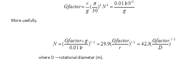
    The centrifugal force acting upon a rotating body is proportional to the radius of rotation and to the square of the velocity:               
 China CNC machining

    
The gravitational force on the same mass would be given by:

 China CNC machining

Hence the factor by which the normal force of gravity is multiplied during rotation is given by:
 China CNC machining

Expressed in the more convenient speed units of revolutions per minute, N, the expression becomes:
 china machining manufacturer

  Although centrifugal forces exceeding 200G are attained in some cases, most practice is empirically based within the range 10-150G, the highest values being used for open bore cylindrical components of small diameter and the lowest for semicentrifugal and pressure castings. Speeds generating forces of 60-80G are most commonly quoted for true centrifugal castings. As previously emphasized, however, the optimum value of centrifugal force diminishes with increasing diameter.    
    Cumberland quotes values of 33G for a wide range of plain vertical axis castings and 15G for semi-centrifugal castings in sand moulds, for which lower speeds suffice since there is no longer dependence on centrifugal force to shape the casting. Thornton gives values of 50-100G for die cast and 25-50G for sand castpots and shaped castings.     

    This is a process where the mould is rotated rapidly about its central axis as the metal is poured into it. Because of the centrifugal force, a continuous pressure will be acting on the metal as it solidifies. The slag, oxides and other inclusions being lighter, get separated from the metal and segregates toward the centre.  China metal parts machining There are three main types of centrifugal casting processes. They are: true centrifugal casting, semi-centrifugal casting, centrifuging.      

2015年3月1日星期日

Vacuum Casting and Continuous Casting

Vacuum Casting and Continuous Casting
 Vacuum Casting
 Vacuum casting is similar China CNC machining to Low Pressure Die Casting in that a permanent mould is linkedto a crucible of molten metal by a riser tube, but instead of pressure being applied to themolten metal, a vacuum is created in the mould cavity, thus drawing the metal up into the cavity.
 Continuous Casting
  Generally the starting point of any structural steel product is the ingot which is subsequently rolled through number of mills before a final product. However, the wide adoption of continuous casting has changed that scenario by directly casting slabs,billets and blooms without going through the rolling process. This process is fast and also economical.
   Continuous casting is the process whereby molten steel is solidified into a semifinished billets, blooms, China CNC machining or slabs for subsequent rolling in finishing mills.
In continuous casting, liquid steel is transferred in a ladle to the casting machine. When the casting operation starts, the sliding shutter at the bottom of the ladle is opened and the steel flows at a controlled rate into the tundish and from the tundish into one or more molds The liquid steel is poured into a double walled, bottomless water cooled mould where a solid skin is quickly formed and a semi-finished skin energy form the open mould bottom. The skin formed in the mould is about 10 to 25 mm in thickness and is further solidified by intensive cooling with water spays as casting moves downwards. About 55 percent of the world's liquid steel production is solidified in continuous casting processes, the most widely used of which feeds liquid steel continuously into a short, water-cooled vertical copper mold and, at the same time, continuously withdraws the frozen shell, including the liquid steel it contains. 
                Fig. 11.9 Schematic of continuous casting process   

 China precision machining

 A typical arrangement of continuous casting plant is shown schematically in Fig. 11.9. The molten steel is collected in a ladle and kept over a refractory lined intermediate pouring vessel named tundish. The steel is taken poured into water cooled vertical cooper moulds which are 450 to 750 mm long. Before starting the casting a dummy starter bar is kept in the moulds bottom as shown in Fig.11.9. After starting the casting process as the metal level rises in the mould to a desirable height, the starter bar is withdrawn at a rate equal to the steel pouring rate. The initial metal freezes onto the starter bar as well as the periphery of the mould. This solidified shell supports the liquid steel as it moves downwards. This steel shell is mechanically supported (rollers) as it moves down through the secondary cooling zone where water is spried onto the shell surface to complete the solidification process. After the casting is completely solidified, it is cut to the desired lengths by a suitable cutoff apparatus.
  To appreciate fully the substantial benefits of continuous casting it is necessary to review some aspects of modern steelmaking and the older process of ingot casting. 
 In both processes, molten steel (usually called a “heat”) is prepared or an electric furnace. The in an oxygen furnace, an open-hearth furnace molten steel is next transferred in a ladle to either a nearby ingot or continuous casting facility. 

 Various types of ingots are prepared, in both processes, depending on the size and shape of the final steel products to be manufactured. China CNC machiningThree types of ingots are made: billets, blooms and slabs. Slabs are used to make plate and other flat products. Billets and blooms are used to make structural shapes, round products and tubes.