2015年2月26日星期四

Ceramic Mold Casting

Ceramic Mold Casting
Similar to plaster mold casting, China precision machining the pattern used in ceramic mold casting is made of plaster, plastic, wood, metal or rubber. A slurry of ceramic is poured over the pattern. It hardens rapidly to the consistency of rubber. This can be peeled of the pattern, reassembled as a mold. The volatiles are removed using a flame torch or in a low temperature oven. It is then baked in a furnace at about 1000 °C (1832 °F) yielding a ceramic mold, capable of high temperature pours. Additionally, the pour can take place while the mold is until hot.
Tolerances can be held to 0.4 %, surface finishes can be better than 2 - 4 μm (.075 - .15 μin). Add 0.3 mm (.012 in) for parting line tolerances. Wall thickness can be as small as 1.25 mm (.050 in), and the weights can range from 60 g (2oz) to a ton. Draft allowance of 1° is recommended.
This process is expensive, but can eliminate secondary machining operations. Typical parts made from this process include impellers made from stainless steel, bronze, complex cutting tools, plastic mold tooling.
Procedure:
Models made of clay, wood or plaster must be coated with 2 or 3 layers of thinned down orange shellac.
Step 1: First you must study the object from which you are to make the mold, to establish the Parting Line. Draw a line on the object with a dye-marking felt tip pen.
Step 2: Place the object on your Work Board so your parting line is somewhat parallel to your work surface. Proceed to Clay-Up with water base modeling clay around the object to your parting line, extend out for one inch from the widest points.
Step 3: When clay is all in place, smooth and leather hard, square off clay as shown. Using a soft brush, apply two thin coats of Orange Shellac over the object and the top surface of the clay parting line. After 15-20 minutes, apply talcum powder, dusting lightly.
Step 4: Apply Parting Agent with a soft brush covering the entire surface. Dry your brush and pick up all excess Parting Agent, leaving a very slick surface on the object and parting line clay.
China precision machining
Step 5: Prepare your casting boards, wiping each with Parting Agent on front surface and edges. Assemble as shown with "C" Clamps. With wooden tool, seal edges where clay parting line meets the insides of the board as shown.
Step 6: READY FOR CASTING. For the size of the object shown in these drawings and the apparent bulk of parting line around the model, we will use the following proportions: With your 1 gallon plastic jar, weigh out 1 1/2 lbs. of No.1 Pottery Plaster
Step 7: Let the plaster soak for 3-5 minutes, then mix with your Drill Motor Mixer. Mix for about 1 1/2 minutes, then pour over boxed pattern. Plaster should cover at least 1 inch over the highest point on the Model.
Step 8: After 20 minutes, take casting boards apart, scrape off top of plaster and bevel the edges slightly. Grasp opposite sides of the plaster/clay mold and gently twist to loosen clay from the work board as shown. Turn mold over and proceed to lift off clay from model and plaster half of the mold.
China precision machining
Step 9: If orange shellac transfers to plaster half, clean with alcohol. Clean all clay particles from the mold surface. Now is the time to carve Keys into the plaster parting line. You can make Keys several ways - round end of large spatula, a coin (nickel or quarter).
Step 10: Prepare your casting boards again, dust the model and parting line area with talcum, brush on parting agent as in Step 4. Assemble the boards as in Step 5 with "C" Clamps and repeat Steps 6 and 7 for casting the second half of the mold. Let the plaster set for 1/2 hour, remove the casting boards, scrape top of the mold, bevel the edge and corners.
Step 11: Now you are ready to open the mold. Scrape off any plaster that may have run down the side of the first half of the mold. Using a flat end screwdriver or a wooden wedge, insert it at the parting line; tap it gently with the hammer. As soon as the mold starts to part, turn the mold over and repeat the process. When the mold is loose, grasp each half and gently pry apart.
Step 12: The model will usually stay in half of the mold. At this point, how accurate you were with your parting line, what material your model was made of , and how hard or soft that material was, will dictate how easy or hard it will be to get the model out of the half plaster mold.
China precision machining
Step 13: If the model was made of clay, you can ease it out by using the screwdriver. But if you have to do any prying like a lever, place a flat piece of wood under your screwdriver so you won't chip the plaster mold. If your model is made of metal, glass or ceramic, you might have to use other means, such as air pressure or tapping all around the model with a rubber mallet. In some cases, you have chipped out the model thus destroying it. But keep in mind, that at this point the mold is the main object because a good, China precision machining usable mold can reproduce 50 to 150 objects.
Step 14: With both halves now clean of any particles, we now determine where to carve in your Pour Hole. It can be in one half or in both halves as shown. Bevel the outer edge of the parting line on both halves and bevel all outside edges of the mold. This keeps that edge from chipping.
China precision machining
Step 15: At this time, China precision machining check each half of the mold for any under-cuts that can be cut back. Let your mold dry out for 4 or 5 days depending on your weather conditions. NOW YOU HAVE A MOLD.

2015年2月24日星期二

Squeeze Casting and Lost Foam Casting

Squeeze Casting and Lost Foam Casting
     Squeeze China precision machining casting also known as liquid metal forging, is a combination of casting and forging process  The molten metal is poured into the bottom half of the pre-heated die. As the metal starts solidifying, the upper half closes the die and applies pressure during the solidification process. The amount of pressure thus applied is significantly less than used in forging, and parts of great detail can be produced.

 Coring can be used with this process to form holes and recesses. The porosity is low and the mechanical properties are improved. Both ferrous and non-ferrous materials can be produced using this method.              
 Fig. 6.12 Schematic of squeeze casting process  
 China precision machining

 Lost Foam Casting
    Lost foam casting allows the production of complex parts. The process produces complex parts and reduces finish machining of the part produced by lost foam casting.
  To make lost foam casting, a foam pattern of the finished part is made.
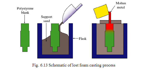
  The pattern is dipped into a water solution containing a suspended refractory.  The refractory material coats the foam pattern leaving a thin heat resistant layer. Sand is poured around the pattern and provides mechanical support to the thin refractory layer.   Molten metal is then poured into the mold, and the molten metal melts and vaporizes the foam. When the metal becomes solid, it is removed from the sand, thus the name lost foam casting.   Lost foam castings may be of any shape or size. Materials commonly used in lost foam casting are Aluminum, iron, steel and nickel alloys.  The Lost Foam casting process originated in 1958 when H.F. Shroyer was granted a patent for a cavity-less casting method,China precision machining using a polystyrene foam pattern embedded in traditional green sand. 
   The polystyrene foam pattern left in the sand is decomposed by the poured molten metal.  The metal replaces the foam pattern, exactly duplicating all of the features of the original pattern.   Like other investment casting methods, this requires that a pattern be produced for every casting poured because it is evaporated (“lost”) in the process.    
The basic steps to the process include (Fig. 6.13):
 1. A foam pattern and gating system are made using a foam molding press 
2. The foam pattern and the gating system are glued together to form a cluster of patterns
 3. The cluster is coated with a permeable refractory coating and dried under controlled conditions 
4. The dried, coated cluster is invested in a foundry flask with loose, unbonded sand that is vibrated to provide tight compaction 
5. The molten metal is poured on to the top of the gating system which directs the metal throughout the cluster and replaces the foam gating and patterns
6. The remaining operations such as, shake out, cut-off,
grinding, heat treat, etc. are straightforward and similar to other casting processes.   
Fig. 6.13 Schematic of lost foam casting process       
 China precision machining


Generally, all ferrous and non-ferrous materials can be successfully cast using the Lost Foam process.  Because the foam pattern and gating system must be decomposed to produce a casting, metal pouring temperatures above 1000°F are usually required. Lower temperature metals can be poured, but part size is limited. China precision machining In addition, very low carbon ferrous castings will require special processing.  

2015年2月22日星期日

Investment Casting

 Investment Casting
 This is the process where the mould is China precision machining  prepared around an expendable pattern. Casting processes in which the pattern is used only once are variously referred to as "lost-wax" or "precision-casting" processes. In any case they involve making a pattern of the desired form out of wax or plastics (usually polystyrene).
 The first step in this process is the China precision machining   preparation of pattern for every casting made. To do this, molten wax which is used as the pattern material is injected under pressure of about 2.5 MPa into a metallic die which has the cavity of the casting to be made.
  The wax when allowed to solidify would produce the pattern. To this wax pattern, gates, runners and any other details required are appended by applying heat. 
   The process has been described as the lost wax, precision casting, and investment
casting process. The last-dimensional name has been generally accepted to distinguish the present industrial process from artistic, medical, and jewelry applications.
  The basic steps of the investment casting process are as follows  
 1. Production of heat disposable patterns, usually in wax or plastic.
 2. Assembly of these patterns onto a gating system.
3. Investing, or covering the pattern assembly with ceramic to produce a
monolithic mold. 
4. Melting out the pattern assembly to leave a precise mold cavity.
 5. Firing the ceramic mold to remove the last traces of the pattern material, to fire the ceramic andChina precision machining   develop the high temperature bond, and to preheat the mold ready for casting.
6. Casting.
 7. Knock-out, cut off, and finishing. 
 China CNC machining


2015年2月13日星期五

Die Casting

   Die Casting
     Die casting involves the preparation of components by injecting molten metal at high pressures into a metallic die.China CNC machining  Die casting is closely related to permanent mould casting, in that both the processes use reusable metallic dies. In die casting, as the metal is forced in under pressure compared to permanent moulding, it is also called pressure die casting'. Because of the high pressure involved in die casting, any narrow sections, complex shapes and fine surface details can be easily produced.

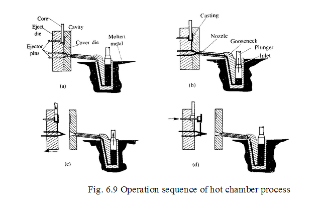
    In die casting, the die consists of two parts. One called the stationary die or cover die which is fixed to the die casting machine. China CNC machining  The second part called the ejector die is moved out for the extraction of the casting. The casting cycle starts when the two parts of the die are apart. The lubricant is sprayed on the die cavity manually or by the auto lubrication system. The two die halves are closed and clamped. The required amount of metal is injected into the die. After the casting is solidified under pressure the die is opened and the casting is ejected.
    The die casting machines are of two types: hot chamber die casting, and cold chamber die casting. The main difference between these two types is that in hot chamber, the holding furnace for the liquid metal is integral with the die casting machine, whereas in the cold chamber machine, China CNC machining the metal is melted in a separate furnace and then poured into the die casting machine with a ladle for each casting cycle which is also called 'shot'.
  Fig. 6.9 Operation sequence of hot chamber process 
 China precision machining


2015年2月11日星期三

Casting Processes

Casting Processes
  Shell Moulding
   It is a process in which, China precision machining the sand mixed with a thermosetting resin allowed to come into contact with a heated metallic pattern plate, so that a thin and strong shell of mould is formed around the pattern. Then the shell is removed from the pattern and the cope and drag are removed together and kept in a flask with the necessary back up material and molten metal is poured into the mould.
  Generally, dry and fine sand (90 to 140 GFN) which is completely free of the clay is used for preparing the shell moulding sand. The grain size to be chosen depends on the surface finish desired on the casting. Too fine a grain size requires large amount of resin which makes the mould expensive.  the synthetic resins used in shell moulding are essentially thermosetting resins, which get hardened irreversibly by heat. The resins most widely used, are the phenol formaldehyde resins. Combined with sand, they have very high strength and resistance to heat. The phenolic resins used in shell moulding usually are of the two-stage type, that is, the resin has excess phenol and acts like a thermoplastic material. China precision machining During coating with the sand the resin is combined with a catalyst such as hexa-methylene-tetramine (hexa) in a proportion of about 14 to 16% so as to develop the thermosetting characteristics.

  Additives may sometimes be added into the sand mixture to improve the surface finish and avoid thermal cracking during pouring. Some of the additives used are coal dust, pulverised slag, manganese dioxide, calcium carbonate, ammonium borofluoride and magnesium silicofluoride. Some lubricants such as calcium stearate and zinc stearate may also be added to the resin sand mixture to improve the flowability of the sand and permit easy release of the shell from the pattern. 
  The first step in preparing the shell mould is the preparation of sand mixture in such a way that each of the sand grain is thoroughly coated with resin. To achieve this, first the sand, hexa and additives which are all dry, are mixed inside a Mueller for a period 1 min. Then the liquid is added and mixing is continued for another 3min. To this cold or warm air is introduced into the Mueller and the mixing is continued till all the liquid is removed from the mixture and coating of the grains is achieved to the desired degree. 
 The metallic pattern plate is heated to a temperature of 200 to 350 ºC depending on the type of the pattern. It is very essential that the pattern plate is uniformly heated so that the temperature variation across the whole pattern is within 25 to 40 ºC depending on the size of the pattern. A silicone release agent is sprayed on the pattern and the metal plate. The heated pattern is securely fixed to a dump box, as shown in
Fig. 6.7 (a), wherein the coated sand in an amount larger than required to form the shell of necessary thickness is already filled in.   
Fig. 6.7 Shell moulding procedure 
 precise metal parts

     
 When a desired thickness of shell is achieved, the dump box is rotated backwards by 180 so that the excess sand falls back into the box, leaving the formed shell intact with the pattern as in Fig. 6.7 (d). The average shell thickness achieved depends on the temperature of the pattern and the time the coated sand remains in contact with the heated pattern. The actual shell thicknesses required depends on the pouring metal temperature and the casting complexity. This may normally be achieved by trial and error method.  
               Fig.6.8 Shell mould ready for pouring
 China precision machining


 Since the shells are thin, they may require some outside support so that they can withstand the pressure of the molten metal. A metallic enclosure to closely fit the exterior of the shell is ideal, but is too expensive and therefore impractical.

  Alternatively, a cast iron shot is generally preferred as it occupies any contour without unduly applying any pressure on the shell. China precision machiningWith such a backup material, it is possible to reduce the shell thickness to an economical level.  

2015年2月9日星期一

Chill

   Chill
  In a casting, metallic chills are used in order to provide progressive solidification or to avoid the shrinkage cavities. China CNC machining Chills are essentially, large heat sinks. Whenever , it is not possible to provide a riser for a part of the casting which is heavy, a chill is placed close to it as shown in Fig. 5.29, so that more heat is quickly absorbed by the chill from the larger mass making the cooling rate equal to that of the thin sections. Thus, this dose not permit the formation of a shrinkage cavity. But use of a chill means essentially providing higher cooling rate which is also likely to form a hard spot at the contract area with the chill and may therefore cause a problem if that area needs further processing way of machining.   


  Melting Practice
 The preparation of molten metal for casting is referred to simply as melting. Melting is usually done in a specifically designated area of the foundry, and the molten metal is transferred to the pouring area where the molds are filled. After moulding, melting is the major factor which controls the quality of the casting. There are a number of methods available for melting foundry alloys such as pit furnace, open hearth furnace, rotary furnace,China CNC machining cupola furnace, etc. The choice of the furnace depends on the cupola in its various forms is extensively used basically because of its lower initial cost and lower melting cost.  
  cleaning
  Cleaning refers to all operations necessary to the removal of sand, scale, and excess metal from the casting. The casting is separated from the mold and transported to the cleaning department. Burned-on sand and scale are removed to be improved the surface appearance of the casting. Excess metal, in the form of fins, wires, parting line fins, and gates,China CNC machining  is removed. Castings may be upgraded by welding or other procedures. Inspection of the casting for defects and general quality is performed 
  Other processes 

Before shipment, further processing such as heat-treatment, surface treatment, additional inspection, or machining may be performed as required by the customer's specifications.  

2015年2月7日星期六

Sprue base well

Sprue base well
  This is a reservoir China precision machining  for metal at the bottom of the sprue to reduce the momentum of the molten metal. The molten metal as it moves down the sprue grains in velocity some of which is lost in the sprue base well by which the mould erosion is reduced.
 This molten metal changes direction and flows into the runners in a more uniform way.   
Runner
 It is generally located in the horizontal plane (parting plane) which connects the sprue to its ingates, thus letting the metal enter the mould cavity. The runners are normally made trapezoidal in cross section. It is a general practice for ferrous metals to cut the runners in the cope and the ingates in the drag. The main reason for this is to trap the slag and dross which are lighter and thus trapped in the upper portion of the runners.
 For effective trapping of the slag, runners should flow full. When the amount of
molten metal coming from the down sprue is more than the amount flowing through the ingates, the runner would always be full and thus slag trapping would take place. But when the metal flowing through the ingates is more than that flowing through the runners, then the runner would be filled only partially and the slag would then enter the mould cavity. 
   Runner extension
  The runner is extended a little further after it encounters the ingate. This
extension is provided to trap the slag in the molten metal. The metal initially comes along with the slag floating at the top of the ladle and this flows straight, going beyond the ingate and trapped in the runner extension.
   Riser  Most of the foundry alloys shrink during solidification. Table 10.1 shows the various volumetric shrinkages for typical material. As a result of this volumetric shrinkage during solidification, China precision machining  voids are likely to form in the castings unless additional molten metal is fed into these places which are termed as hot spots since they remain hot till the end. Hence a reservoir of molten metal is to be maintained from which the metal can flow readily into the casting when the need arises. These reservoirs arecalled risers. 
 As shown in Table 5.6, different materials have different shrinkages
and hence the riser requirements vary for the materials. In grey cast iron, because of graphitization during solidification, there may be an increase in volume sometimes. This if course, depends on the degree China precision machining   of graphitization in grey cast iron which is controlled by the silicon content. 
  In order to make them effective, the riser should be designed keeping the following in mind.
 1. the metal in the riser should solidify in the end. 
 2. the riser volume should be
sufficient for compensating the shrinkage in  the casting. 
      Table 5.6 volumetric liquid shrinkages
  Material            Shrinkage,(%)
Medium carbon steel     2.50 to 3.50
High carbon steel         4.00
 Nickel               6.10
Monel               6.30
Aluminum              6.60
Aluminum alloy (11-13% Si)   3.50
 Aluminum bronze         4.10
 Copper                  4.92
 70-30 brass              4.50
 Bearing bronze           7.3
 Grey cast iron             1.90 to negative
 White cast iron           4.00 to 5.75
 Magnesium              4.20

  Zinc                   6.50

2015年2月5日星期四

Pouring basin

   Pouring basin 
  The molten metal is not directly poured into the mould cavity because it may cause mould erosion.China precision machining  Molten metal is poured into a pouring basin which acts as a reservoir from which it moves smoothly in to sprue. The pouring basin is also able to stop the slag from entering the mould cavity by means of a skimmer or skim core as shown in Fig.5.27. It hold back the slag sand dirt which floats on the top and only allow the clean metal underneath it into the sprue. The pouring basin may be cut into the cope portion directly or a separate dry sand pouring basin may be prepared and used as
shown in Fig.5.27. the molten metal in the pouring basin should be full during the pouring operation, otherwise a funnel is likely to form through which atmospheric air and slag may enter the mould cavity.
   

  (a) Green sand
(b) Dry sand Fig. 5.27 Pouring basin  
 One of the walls of the pouring basin is made inclined at about 45°to the horizontal. The molten metal is poured on this face such that metal momentum is absorbed and vortex formation is avoided. In some special cases the pouring basin may consist of partitions to allow for the trapping of the slag and maintaining constant metal height in the basin.    Sprue 
 China precision machining  Sprue is the channel through which the molten metal is brought into the parting plane where it enters the runners and gate to ultimately reach the mould cavity.
The molten metal when moving from the top of the cope to the parting plane grains in velocity and as a consequence requires a smaller area of cross section for the same amount of metal to flow at the top. If the sprue were to be straight cylindrical as shown in Fig. 5.28(a), then the metal flow not be full at the bottom, but some low pressure area would be created around the metal in the sprue. Since the sand mould is permeable, atmospheric air would be breathed into this low pressure area which would then be carried to the mould cavity. To eliminate this problem of air aspiration the sprue is tapered to gradually reduce the cross section as it moves away from the top of the cope as China precision machining  hown in Fig.5.28(b).  


 (a)Straight sprue

   (b) Tapered  

2015年2月3日星期二

Coremaking


    Coremaking
   China precision machining Cores are the materials used for making cavities and hollow projections which cannot normally be produced by the pattern alone. 
  Any complicated contour or cavity can be made by means of cores so that really intricate shapes can be easily obtained. These are generally made of sand and are even used in permanent moulds. In general, cores are surrounded on all sides by the molten metal and are therefore subjected to much more severe thermal and mechanical conditions and as a result, China precision machining the core sand should be of higher strength than the moulding sand.
As defined earlier, gating system refer to all those elements which are connected
with the flow of molten metal from the ladle to mould cavity. The various elements that are
connected with a gating system are (Fig. 5.26): 
  
  Pouring
  basin
  Sprue 
 Sprue base well
  Runner 
  Runner extension
  Riser
 Chill  
  Fig.
Typical gating system  
In this section the functions and the design of the various elements of a gating system
will be discussed. Any gating system designed should aim at providing a defect
free casting. This can be achieved by making provision for certain requirements while designing the gating system. These are as follows: 
 1.the mould should be completely filled in the smallest time possible without having to raise metal temperature nor use higher metal heads.
 2. the metal should flow smoothly into the mould without any turbulence.
A turbulent metal flow tends to form dross in the mould
 3. unwanted material such as slag, dross and other mould material should not be  allowed enter the mould cavity
 4.the metal entry into the mould cavity should be properly controlled in such a
way that aspiration of the atmospheric air is prevented
5. a proper thermal gradient should be maintained so that the casting is cooled  without any shrinkage cavities or distortions
 6. metal flow should be maintained in such a way that no gating or mould  erosion take place.
 7. the gating system should ensure that enough molten metal reaches the mould  cavity 
8. the gating system design should be economical and easy to implement and  remove after casting solidification 
9. ultimately, the casting yield should be maximized 
  ToChina precision machining  have all these requirements together is a tall order, still a mould designer should strive to achieve as many of the above objectives as possible. Before going into the mechanics of gating design, let us describe some of the functions and types of various gating system elements


2015年2月1日星期日

Renoho Precision Machinery Technology Co.,Ltd: Basic Design of Metal Processes

Renoho Precision Machinery Technology Co.,Ltd: Basic Design of Metal Processes: Basic Design of Metal Processes  Patternmaking   The pattern is a physical model of the casting used to make the mold.     China prec...

Basic Design of Metal Processes

Basic Design of Metal Processes
 Patternmaking
  The pattern is a physical model of the casting used to make the mold. 
  China precision machining The mold is made by packing some readily formed aggregate material, such as molding sand, around the pattern. When the pattern is withdrawn, its imprint provides the mold cavity, which is ultimately filled with metal to become the casting.  
 If the casting is to be hollow, as in the case of pipe fittings, additional patterns, referred to as cores, are used to form these cavities. As has been defined earlier,   China precision machining a pattern is a replica of object to be made by the casting process, with some modification.
 The main modifications are:     
a) the addition of pattern allowances,
(b) the provision of core prints,  
(c) the elimination of fine details which cannot be obtained by casting and hence are to be obtained by further process. 
 Core prints 
 For all those casting where coring is required, provision should be made to support the core inside the mould cavity. One of the methods that is universally followed is to provide core prints where possible. In Fig 5.22 is shown an example of the provision of core prints. The size of the core prints to be provided is to be estimated based on the specific casting.  


 Fig.5.22 Typical job, its pattern and the mould cavity 
Moulding Materials 
 A large variety of materials are used in foundries for manufacturing moulds and cores. They are:  Moulding sand,   System sand (backing sand),  Rebounded sand,  Facing sand,  Parting sand,   Core sand.   
 The properties of moulding sand
  The choice of moulding materials is based on their processing properties. The properties that are generally required in moulding materials are:  
 Refractoriness: it is the ability of the moulding material to withstand the high temperatures of the molten metal so that it dose not cause fusion.   Green strength: The moulding sand that contains moisture is termed as green sand.
 The green sand should have enough strength so that the constructed retains its shape.   Dry strength: When the moisture in the moulding sand is completely expelled, it is called dry sand. When molten metal is poured into a mould, the sand around the mould cavity is quickly converted into dry sand as the moisture in the sand immediately evaporates due to the heat in the molten metal. At this stage, it should retain the mould cavity and at the same time withstand the metallostatic forces.     Hot strength: After all the moisture is eliminated, the
sand would reach a high temperature when the metal in the mould is still in the liquid state. The strength of the sand that is required to hold the shape of the mould cavity then is called hot strength.  Permeability: During the solidification of a casting, large mounts of gases are to be expelled from the mould. The gases are those which have been absorbed by the metal in the furnace, air absorbed from the atmosphere and steam and other gases that are generated by the moulding and core sands. If the gases are not allowed to escape from the mould, they would be trapped inside the casting and cause defects. The moulding
sand should be sufficiently porous so that the gases are allowed to escape from the mould. This gas evolution capability of the moulding sand is termed as permeability. 

  Beside those specific properties, the moulding sand should also have collapsibility so that during the construction of the solidified casting, it dose not provide any resistance which may result in cracks in the casting, they should be reusable and should have good thermal   China precision machiningconductivity so that heat from the casting is quickly transferred.